You are in:

300m
First
Service |

Ford
Anglia 105E - 300 Mile (500 km) First Check and Service
Schedule
It is impossible
to over emphasise the importance of correct
lubrication, inspection and running adjustments,
if you wish to obtain the best level of service
from your Ford Anglia and Ford Prefect. At the
first 300 Miles (500 km) it is advisable to have
a “1000 Mile Service” carried out on
the car, with particular attention to the first
six points. (In the later Handbooks and Manuals,
this periodic service was extended to the first
500 miles).
The 300 Mile service incorporates:
(Key: This Colour = Daily Service items, This Colour
= Weekly
Service items, This Colour = 1000 Mile
Service Items)Change the Engine Oil
Change the Engine Oil Filter Element
Check Cylinder Head Bolts
Check and Adjust Valve Clearances (if
necessary)
Check the Wheel Nuts
Check the Clutch Adjustment at Operating Cylinder
Check the Radiator Level
Check the Petrol Level in the Tank
Check the Windscreen is Clean
Check the Battery Electrolyte Level
Check the Brake and Clutch Fluid Reservoir Levels
Check the Operation of all Lights
Check the Tyre Pressures
Check the Gearbox Oil Level
Check the Rear Axle Oil Level
Check the Steering Box Oil Level
Check
the Fan Belt Adjustment
Check the Clutch Adjustment at Operating Cylinder
Check the Windscreen Washer Level (where
fitted)
Check the Seat Belts for Security and Wear (where
fitted)
Lubricate all Grease Gun Points (L1 - L5)
Lubricate Linkages and Locks
Lubricate the Distributor
|
Clean the Oil Filler Cap
The oil filler cap also acts as an engine
ventilator and it is advisable to remove any
accumulation of foreign matter from the gauze,
when changing the engine oil.To clean the dry gauze type
cap it is only necessary to wash this in petrol
or paraffin and then dip in engine oil, shaking
out the surplus. Although a small job, this is
quite important as Ford engines do breathe quite
heavily.
|
 |
Change
the Engine Oil
This service item covers both this item and the
next item, which is to drain the oil and change
the oil filter element.Check the oil with the dipstick. If the
oil on the dipstick appears dirty for any reason
before this mileage is reached, the engine should
be refilled with clean new oil and the filter
element replaced.
Place
a suitable container under the sump drain plug.
Do not overlook the fact that there may be up to
4 ½ pints of oil in the sump, so use a drain pan
of sufficient size to hold this quantity of oil.
Remove the sump drain plug. The engine oil will
drain out more easily when warm and, at the same
time, will tend to remove any foreign matter
present in the sump.
When
all of the oil has been drained away, replace the
drain plug. A good quality flushing oil may be
used in the engine, but in NO CIRCUMSTANCES
SHOULD PARAFFIN BE USED TO FLUSH OUT THE
CRANKCASE.
Replace
the oil filter element (as detailed below). Pour
the appropriate quantity of correct grade oil in through the filler
neck, run the engine for a short while, allow to
stand, and then check the oil level on the dipstick,
topping up as required.
Warning –
Do not pour old oil down the sink or into any
water drain. Place it in an old container and
dispose of it at your local Council Oil Recycling
Centre.
|
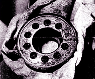
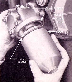
Change the Engine Oil Filter
Element
The oil filter
is fitted direct onto the cylinder block, no
connecting pipes to the engine being required. To
change the element, first drain the oil (as
above) and undo the hexagon headed bolt retaining
the filter unit to the cylinder block, and
withdraw the filter assembly. Withdraw the filter
element from the casing and replace it with the
new element.A new rubber sealing ring
is supplied with each element. Remove the
existing ring, then locate the new ring in the
groove at four diametrically opposite points. Do
not fit the gasket at one point and then work it
round the groove, as the rubber may stretch, thus
leaving a surplus, which could cause an oil leak.
Refit the filter
assembly to the cylinder block and retighten the
bolt.
|
 |
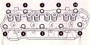
Check Cylinder Head Bolts
To check the cylinder head bolts, remove the
valve rocker cover by undoing the four retaining
screws. Be careful not to damage the rocker cover
gasketThe cylinder head bolts should be
tightened at this mileage in the sequence
illustrated opposite.
Take care not to over tighten the
cylinder head bolts as this will only impose
excessive strain. If possible, use a torque
wrench and tighten the bolts to 65-70 lb/ft
When replacing the
rocker cover ensure that the gasket is correctly
positioned on the cylinder head to avoid oil
leaks
|
 |
Check
the Valve Clearances and Adjust (if
necessary)
Open the
bonnet and listen to the engine carefully. If
there is a clattering sound from the top of the
engine, and the sound increases both in loudness
and noise as the engine speed is increased, then
it is best to check and adjust the valve
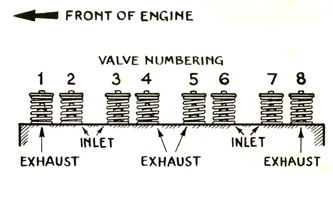
clearances. Each cylinder has a pair of valves;
one inlet and one exhaust, and each valve is
operated by its rocker arm.
To check or adjust the valve clearances, remove
the valve rocker cover by undoing the four
retaining screws. Be careful not to damage the
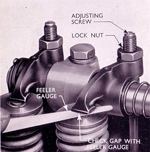
rocker cover gasket.The valve clearance
adjusting screws will then be exposed, and the
clearance should be adjusted to 0.010 in (0.254
mm) for the inlet valves and 0.017 in (0.432 mm)
for the exhaust valves, with the engine at normal
operating temperature.
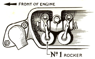 
In
order to ensure that each valve is fully closed,
check as follows:-
|
Valves Open
1 and 6 .. .. .. .. .. .. .. .. .. .. .. .. .. ..
.. .. .. .. .. .. .. .. ..
3 and 8 .. .. .. .. .. .. .. .. .. .. .. .. .. ..
.. .. .. .. .. .. .. .. ..
2 and 4 .. .. .. .. .. .. .. .. .. .. .. .. .. ..
.. .. .. .. .. .. .. .. ..
5 and 7 .. .. .. .. .. .. .. .. .. .. .. .. .. ..
.. .. .. .. .. .. .. .. ..
Exhaust Valves Nos 1, 4, 5 and 8 |
Valves to Adjust
3 and 8
1 and 6
5 and 7
2 and 4
Inlet Valves Nos 2, 3, 6 and 7 |
| To adjust a rocker, slacken
off the adjusting screw locknut and insert a
feeler blade between the toe of the rocker and
the valve end. Turn the adjusting screw until the
correct clearance has been obtained and tighten
the locknut. Recheck the gap after tightening the
locknut to make sure it hasn’t moved. When replacing the rocker
cover ensure that the gasket is correctly
positioned on the cylinder head to avoid oil
leaks.
|
 |
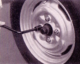
Wheel Nuts
It is good practise to check all of the Wheel
Nuts on a regular basis for tightness. Do not use
any sort of extension bar, as ordinary pressure
exerted on the handle of the wheel brace supplied
with your vehicle is sufficient. |
 |
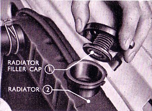
Check the Radiator Level
The cooling system is pressurised by means of a
spring loaded pressure radiator cap. If the
vehicle has been running and is hot, allow it to
cool down before attempting to remove the
radiator cap. Warning
– Do not remove the radiator cap when the
water is near boiling point, as this may cause
water and steam to be blown back out of the
filler neck at pressure, possibly causing
personal injury.
Remove the
radiator filler cap slowly, by pushing down
slightly and twisting it to release it. Check the
water level in the top of the radiator. Top up as
necessary with the correct anti-freeze / water
mixture, to approximately one inch (25 mm) below
the bottom of the filler to allow for expansion
of the coolant as the engine warms up. Once the
radiator has been topped, the radiator cap can be
replaced.
|
 |
Check the
Petrol Level in the Tank
Before any journey ensure that the level of fuel
in the tank is sufficient for immediate needs.
This can easily be ascertained by switching on
the ignition, and observing the reading of the
fuel gauge fitted on the instrument panel. It is
advisable not to let the level in the petrol tank
fall too low as any dirt or particles within the
tank / petrol will find their way into the fuel
lines. If there is insufficient fuel for
immediate needs then the petrol tank needs to be
topped up. Check
the Windscreen is Clean
To ensure you have good visibilty whilst driving,
clean your windscreen with a clean dry cloth and
an appropriate vehicle glass cleaner.
|
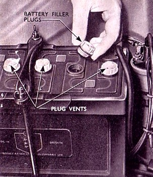
Check the Battery
Electrolyte Level
The battery is
accessibly located under the bonnet, within the
engine compartment. Remove the filler caps and
check that the electrolyte in each cell is 1/4 to
3/8 in (6.35 to 9.525 mm) above the tops of the
plates. If below this level add distilled water
as necessary. (In cold weather the distilled
water should only be added immediately before
running the engine, so that when the generator is
charging, the water and electrolye will mix and
prevent freezing.) The filler caps can now be
refitted. Keep the battery filler
caps and battery connections tight and the top of
the battery clean.
A
coating of petroleum jelly will protect the
battery terminals. Occasionally check the battery
clamp to ensure that the mounting wings nuts are
tight and the battery is still secure in the
battery tray.
Excessive
use of distilled water by the battery is usually
an indication of an unduly high
generator-charging rate and you should consult an
Auto Electrician or your Authorised Ford Dealer
and have the charging system checked.
|
 |
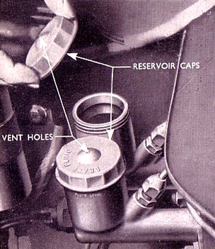
Check the Brake and Clutch
Fluid Reservoir Levels
The brake and clutch fluid reservoirs are located
in the engine compartment on the driver’s
side of the car and are integral with their
master cylinders. When checking or replenishing
the system wipe the sides of the reservoirs and
caps with a clean dry cloth to prevent any dirt
entering the system. Do not use a cloth that is
greasy or has been soaked in petrol or paraffin
etc. Remove each cap by unscrewing it and
top up if necessary to the level indicated on the
reservoir casing (approximately 5/8 in (16mm)
from the rim). Use only the correct brake fluid, obtainable from your
Authorised Ford Dealer.
Warning
– MINERAL OILS MUST NOT BE USED IN ANY
CIRCUMSTANCES FOR TOPPING UP THE RESERVOIRS.
|
 |
Check the Tyre Pressures
It is necessary to keep the tyre pressures at the
specified figures, checking the pressures at
least once a week is recommended. It's not always
apparent that air is being lost, but it generally
escapes at the rate of up to two pounds of air
every month. More air is usually lost during warm
weather, so more regular checks are needed when
temperatures rise. Incorrect tyre pressures or
excessive wear can adversely affect the steering
and braking of the car. The tyre pressure should
be checked before a run whilst the tyres are
cold, as a hot tyre will give a higher reading.
If the tyres are checked hot, do not, in any
circumstances, bleed off this increase in
pressure.
The air pressure in the tyres has a pronounced
effect on the action of the brakes, as well as
the correct operation of the front suspension and
steering gear. |
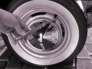 |
To check the
pressure of a tyre, remove the valve cap and
press a suitable tyre gauge firmly ito place. If
necessary sufficient air should be added to bring
the tyre pressure up to the amount specified. Do
not forget to check the pressure of the spare
wheel.
Do not forget to refit the valve cap. Unequal or insufficient
pressure results in rapid wear, uneven braking
and heavy steering.
The correct tyre
pressures are:
Anglia Saloon - 22lb/sq in (1.54 kg/sq cm) front
and rear
Anglia Estate – 24 lb/sq in (1.69 kg/sq cm)
front and 30 lb/sq in (2.11 kg/sq cm) rear
Anglia 5cwt Van - 24 lb/sq in (1.69 kg/sq cm)
front and rear
Anglia 7cwt Van - 24 lb/sq in (1.69 kg/sq cm)
front and 30 lb/sq in (2.11 kg/sq cm) rear
More information about tyres is contained in the General
Maintenance for Wheels and Tyres Page
Check the
Operation of all Lights
Operate all of the lights one at a time and check
that they operate correctly and that there are no
blown bulbs. As well as it being unsafe to drive
without operating lights, it is also an offense
in the UK.
To replace any of the bulbs, follow the steps at
the General Maintenance for
Lights
Page.
|
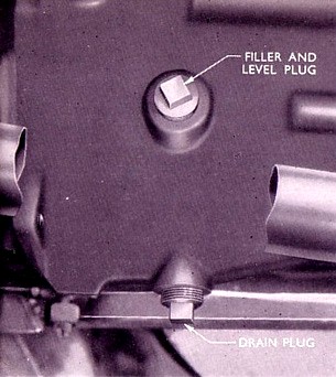
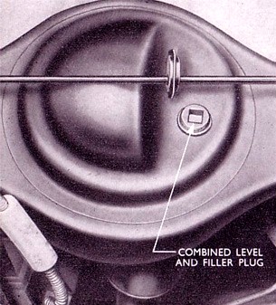
Check the Gearbox Oil Level
With the car
standing on level ground, remove the combined
filler and level plug, which is located on the
side of the gearbox. Check the oil level, which
should be level with the bottom of the filler
plug hole. If required, top up with Extreme Pressure Gear Oil. The oil may be added by
means of a suitable gun through the combined
level and filler plug until the level reaches the
bottom of the filler plug hole. Replace the
filler plug and tighten securely.The
oil in the gearbox should be maintained to the
level of the filler plug at all times.
Insufficient oil will accelerate wear on the
gearbox parts, whilst too high an oil level may
result in the oil passing into the clutch housing
with consequent ill effects on the clutch facings
|
 |
Check the Rear Axle Oil
Level
With the car standing on level ground, remove the
combined filler and level plug, which is located
halfway up the axle (on earlier cars there is
also a drain plug located in the bottom of the
axle.) Check the oil level, which should be level
with the bottom of the filler plug hole. If
required top up with the correct Grade of Oil until the level reaches
the filler plug hole.NOTE
– Only Hypoid and not
ordinary gear oil is to be used in the rear axle.
Replace the filler
plug and tighten securely. Periodically check the
tightness of the filler plug.
|
 |
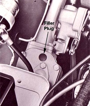
Check the Steering Box Oil
Level
With the car standing on level ground, remove the
rubber plug on top of the steering box. Check the
oil level, which should be level with the filler
plug hole. If required top up with Extreme Pressure Gear Oil until the level reaches
the filler plug hole.Replace the rubber plug.
The Steering Gear is of the worm and nut and
apart from the periodic lubrication described
above, requires adjustment and attention only at
fairly long intervals
|
 |
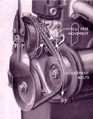 |
Check the Fan Belt
Adjustment
The same V-Shaped belt drives both the generator
and water pump. The belt adjustment is correct
when, as it is pushed and pulled at a point
midway between the generator and water pump
pulleys, the total movement of the belt does not
exceed ½ in (12.7mm). A loose belt causes slip
on the pulleys, while excessive tightness results
in wear on the generator and water pump bearings
and the belt itself.To adjust the fan belt
tension, loosen the two generator lower mounting
bolts, one at the front and one at the rear, then
loosen the adjustment locking screw at the front
of the generator. This will allow the generator
to be moved outwards, the adjustment screw
sliding in the slotted arm.
When the correct
tension is obtained, tighten all three bolts
securely.
|
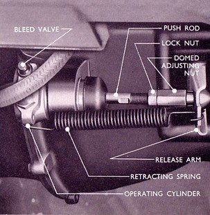 |
Check the Clutch Adjustment
At Operating Cylinder
The amount of free travel on the clutch release
arm should be checked and adjusted if necessary.
The clearance between the end of the clutch
operating rod adjusting nut and the clutch
release arm should be 1/16 in (1.6mm)
Compensation for wear is easily made by adjusting
the length of the clutch operating rod. To obtain
the correct clearance, disconnect the release arm
return spring, slacken the operating rod locknut
and turn the domed adjusting nut at the end of
the push rod clockwise to increase the free
movement and anti-clockwise to reduce it.After
making the adjustment, ensure that the locknut is
tightened and the return spring is re-located.
|
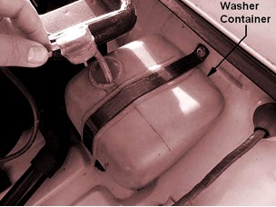 |
Check the Windscreen Washer
Level (where fitted)
The windscreen washer container is located on the
left hand side of the engine compartment on the
bulkhead next to the heater.The
container is made of an opaque plastic and so you
should be able to see whether the windscreen
washer fluid needs topping up. If the level is
low, remove the cap from the container and fill
with a suitable screen wash solution. Refit the
container cap.
|
Check the
Seat Belts for Security and Wear (where
fitted)
Check along the length of the webbing on each
belt to see if there are any nicks or tears in
the material. Sit in the vehicle and then test
the buckle, making sure that it opens and closes
smoothly and does not stick. Gently pull on the
closed buckle to see if it is secure. Check that
the seat belt adjustment works correctly by
adjusting the belt to see that the belt moves
smoothly through the adjuster and does not snag
on anything. (Remember to re-adjust it to your
needs before using the car.)Warning
- If the belts look defective in
anyway, or you are unsure about what to look for,
have the belts checked by your Authorised Ford
Dealer or a trained Mechanic. Do not take risks.
Your life may depend on the security of the seat
belts.
Lubricate
all Grease Gun Points
It is essential that a high-pressure grease gun
be used to force a good quality grease in to
parts equipped with the conical shaped non-return
lubricators (grease nipples).
A
Grease Gun can be purchased from your Authorised
Ford Dealer. To fill the grease gun, remove the
cap and plunger, pack the body with grease
solidly excluding as much air as possible, then
replace the cap and plunger. Use a high grade
grease for all bearing surfaces.
It
is important that dirt and old grease are cleaned
from around the lubricators before applying a
grease gun to them.
The
lubrication Chart below shows the approximate
position of the lubricators.
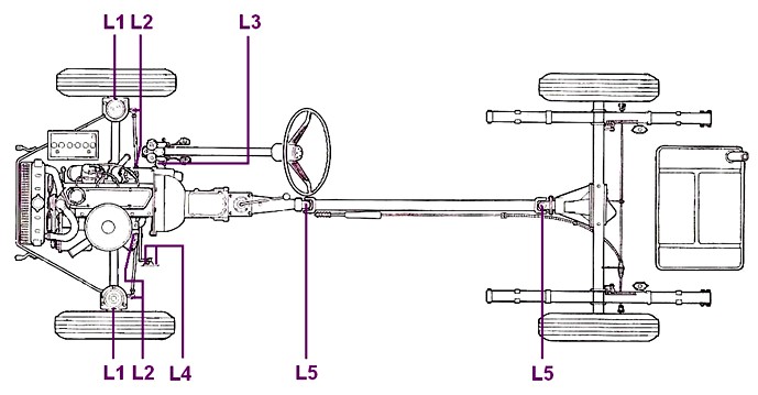
For convenience
the grease gun points are also briefly described
separately after the chart.
|
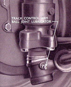
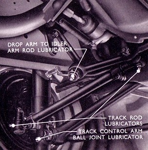
Grease Gun Point –
Track Control Arm - (L1)
The ball joint at the outer end of each track
control arm support is fitted with a lubricator,
which can be reached from beneath the front of
the car, forward of the front suspension cross
tube.
Grease
Gun Point – Track Rods - (L2)
The ball joint at each end of the right and left
hand track rods are fitted with grease gun
lubricators.
|
 |
Grease Gun Point –
Steering Arm to Idler Arm Rod - (L3)
A lubricator is fitted at each end of this rod to
facilitate lubrication at the ball joints.
Grease Gun
Point – Idler Arm (L4)
The upper support bearing on the idler arm
bracket has a lubricator fitted in the centre of
the retaining cap nut
|
 |
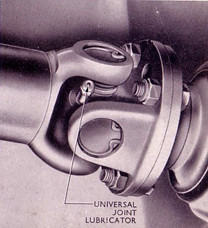
Grease Gun Point –
Universal Joints - (L5)
Each universal joint is fitted with a lubricator
at the centre of the spider. Apply a gun
containing SAE 250 oil or multi purpose lithium
base grease at these points and lubricate as
necessary |
 |
Lubricate
Linkages and Locks
A few drops of light oil should be applied to the
accelerator linkage bearings, hand brake
clevises, bonnet hinges, door hinges and locks,
etc.The
door locks may be lubricated through a small hole
in the rear edge of each door, above the lock.
Make sure that all runs or drips of oil that are
visible on the doors are wiped away with a clean
dry cloth to prevent the soiling of clothing when
entering the vehicle.
|
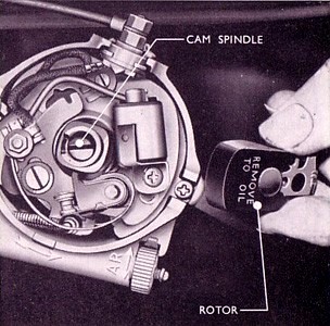
Lubricate the Distributor
Release the two spring clips and remove the
distributor cap and rotor. Apply one or two drops
of engine oil at the cam retaining screw and
spindle to lubricate the distributor shaft
bearings.Apply a thin film of petroleum jelly to
the contact breaker cam and lubricate the contact
breaker pivot post with a small film of engine
oil, ensuring that the contact breaker points are
not contaminated. |
 |
Information taken from Various Ford
Anglia Instruction Books and Handbooks.
Warning -
The Health and Safety bit.
Please note your health may be at
risk if you do not take sensible safety
precautions. Never work under an unsupported
vehicle, do not take shortcuts. If you feel that
the task is beyond your capabilities, then employ
the services of a trained professional. The Owner
of this Website nor the author cannot be held
responsible for any accidents or injury arising
from advice given on this webpage. Safety advice
can be obtained from the RoSPA.
|

|
|