You are in:

5,000m
Check
and Service |

Ford
Anglia 105E - 5,000 Mile (8,000 km) Check and
Service Schedule
t is impossible
to over emphasise the importance of correct
lubrication, inspection and running adjustments,
if you wish to obtain the best level of service
from your Ford Anglia and Ford Prefect. Every
5000 miles (8000 km) or twice yearly, whichever
occurs first, a more comprehensive service should
be carried out.
The 5000 Mile service also incorporates:
(Key: This Colour = Daily Service items, This Colour
= Weekly
Service items, This Colour = 1000 Mile
Service Items)Check the Engine Oil Level
Check the Radiator
Level
Check the Petrol
Level in the Tank
Check the Windscreen is Clean
Check the Battery Electrolyte Level
Check the Brake and
Clutch Fluid Reservoir Levels
Check the Operation
of all Lights
Check the Tyre
Pressures
Check the Gearbox Oil
Level
Check the Rear Axle
Oil Level
Check the Steering
Box Oil Level
Check the Fan Belt
Adjustment
Check the Clutch
Adjustment at Operating Cylinder
Check the Windscreen
Washer Level (where fitted)
Check the Seat Belts for
Security and Wear (where fitted)
Lubricate all Grease Gun
Points
Lubricate all Linkages
and Locks
Lubricate the Distributor
Clean the Oil Filler Cap
Change the Engine Oil
Change the Engine Oil Filter
Change the Gearbox Oil
Change the Rear Axle Oil
Lubricate Generator Rear Bearing
Top up Front Suspension Units
Top up Rear Shock Absorbers (where applicable)
Front Suspension Strut Tops
Check the Rear Spring "U" Bolts
Clean the Air Cleaner
Clean the Fuel Pump
Clean and Adjust Contact Breaker Points (if
necessary)
Clean and Adjust Sparking Plugs
Clean the Distributor Cap
Check and Adjust Ignition
Varying Ignition Settings for Different Fuels
Carburettor Adjustment
Check and Adjust Valve Clearances (if necessary)
Clean Repack and Adjust Front Wheel Bearings
Reposition the Road Wheels (if necessary)
Check and Adjust the Front Brakes
Check and Adjust the Rear Brakes
Check the Brake Lines
|
Clean the Oil Filler Cap
The oil filler cap also acts as an engine
ventilator and it is advisable to remove any
accumulation of foreign matter from the gauze,
when changing the engine oil.To clean the dry gauze type
cap it is only necessary to wash this in petrol
or paraffin and then dip in engine oil, shaking
out the surplus. Although a small job, this is
quite important as Ford engines do breathe quite
heavily.
|
 |
Change
the Engine Oil
This service item covers both this item and the
next item, which is to drain the oil and change
the oil filter element.Check the oil with the dipstick. If the
oil on the dipstick appears dirty for any reason
before this mileage is reached, the engine should
be refilled with clean new oil and the filter
element replaced.
Place
a suitable container under the sump drain plug.
Do not overlook the fact that there may be up to
4 ½ pints of oil in the sump, so use a drain pan
of sufficient size to hold this quantity of oil.
Remove the sump drain plug. The engine oil will
drain out more easily when warm and, at the same
time, will tend to remove any foreign matter
present in the sump.
When
all of the oil has been drained away, replace the
drain plug. A good quality flushing oil may be
used in the engine, but in NO
CIRCUMSTANCES SHOULD PARAFFIN BE USED TO FLUSH
OUT THE CRANKCASE.
Replace
the oil filter element (as detailed below). Pour
the appropriate quantity of correct grade oil in through the filler
neck, run the engine for a short while, allow to
stand, and then check the oil level on the dipstick,
topping up as required.
Warning –
Do not pour old oil down the sink or into any
water drain. Place it in an old container and
dispose of it at your local Council Oil Recycling
Centre.
|
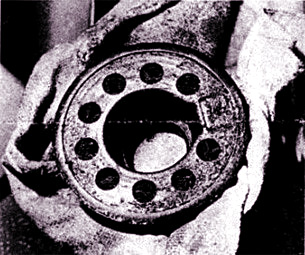
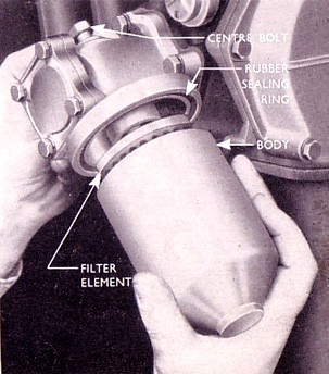
Change the Engine Oil Filter
Element
The oil filter is fitted direct onto the cylinder
block, no connecting pipes to the engine being
required. To change the element, first drain the
oil (as above) and undo the hexagon headed bolt
retaining the filter unit to the cylinder block,
and withdraw the filter assembly. Withdraw the
filter element from the casing and replace it
with the new element.A new rubber sealing ring
is supplied with each element. Remove the
existing ring, then locate the new ring in the
groove at four diametrically opposite points. Do
not fit the gasket at one point and then work it
round the groove, as the rubber may stretch, thus
leaving a surplus, which could cause an oil leak.
Refit the filter
assembly to the cylinder block and retighten the
bolt.
|
 |
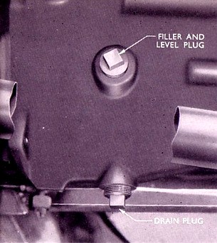 |
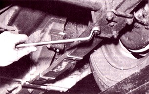
Change the Gearbox Oil
- (at first 5000 Miles only)
Preferably drain the gearbox when the car has
just completed a long run and the oil is warm.
Place a suitable container under the gearbox
drain plug and remove the drain plug at the
bottom of the housing. Replace the plug securely
after draining the oil. Remove the filler plug
and refill the gearbox with Extreme Pressure gear oil of the correct grade until
it reaches the level of the filler plug hole. |
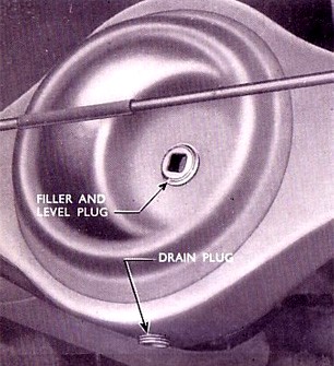 |
Change the Rear Axle Oil
On earlier cars, a drain plug is fitted in the
centre of the axle housing at the bottom. It is
no longer necessary to drain the lubricant at any
service, but it is advisable to check the
tightness of the drain plug when checking the oil
level. For those with earlier cars, the oil may
be drained every 5000 miles if so desired.
Preferably drain the rear axle when the car has
just completed a long run and the oil is warm.
Place a suitable container under the rear axle
drain plug and remove the drain plug. The warm
oil will drain more easily then, bringing with it
any sediment or foreign matter. Replace the plug
securely after draining the oil.Remove the filler plug and
refill the axle housing with the correct grade of
hypoid gear oil until it reaches the level
of the filer plug hole located half way down the
axle housing at the rear. Replace the filler plug
securely when the axle has been filled.
|
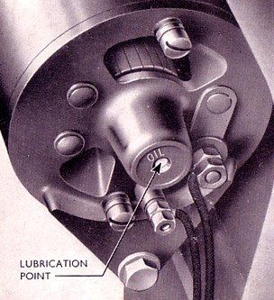 |
Lubricate Generator Rear
Bearing
The front bearing of the generator is packed with
lubricant on assembly and should require no
attention. The life of the front bearing can be
adversely affected by incorrect fan belt
adjustment.The rear bearing is lubricated by
injecting a few drops of engine oil through the
open hole in the centre of the rear end plate. |
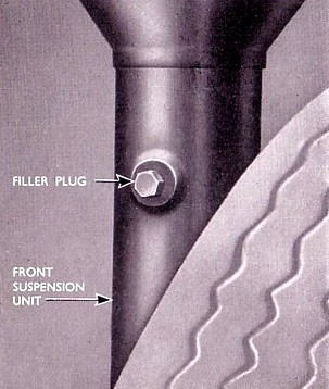
Top up Front Suspension
Units
The car should be parked, unladen standing on
level ground. NOTE - This is most importantRemove
the combined filler and level plug located in the
body of the suspension unit, approximately 3 in
below the coil spring lower seat, at the front or
rear of the unit, and add shock absorber fluid,
Part No M-100502-E, until it reaches the bottom
of the plug hole.
Replace the plug and tighten securely.
NOTE
– On no account should the fluid be added to
the suspension units under pressure.
|
 |
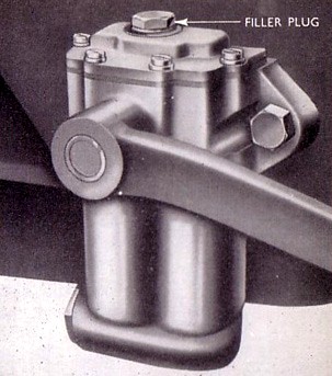
Top up Rear Shock Absorbers
Remove the filler plug located as shown opposite
and top up the shock absorbers, if necessary, to
the level of the filler plug orifice. The design
of the top of the shock absorber allows for
normal expansion of the fluid when it warms up
during use.Use only correct fluid Part
No M-100502-E, which may be obtained through your
Authorised Ford Dealer.
Grease or engine
oil should never be added to the shock absorbers.
Do not lubricate the shock absorber links –
these are rubber bushed and designed to operate
without lubrication.
|
 |
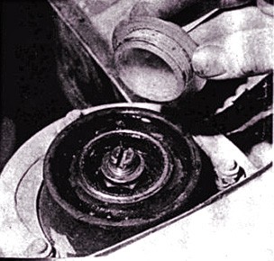
Front Suspension Strut Tops
Although not
specifically mentioned in the Ford handbooks, it
is a good idea to put grease into the bearing at
the top of the front suspension strut every 5,000
miles. Prise off the polythene cover, and pack
with a medium grease of the same grade as used
for the suspension nipples |
 |
Check the Rear Spring
"U" Bolts
Inspect the rear spring "U" Bolt nuts
and tighten if found necessary. Check to ensure
that all accessible bolts and nuts are correctly
tightened.
Tightening torque 20 to 25 lb/ft (2.76 to 3.46
kg/m).Brush any loose material off the rear
springs, which may then be sprayed or brushed
with a penetrating oil for lubrication purposes. |
 |
Clean
the Air Cleaner
This is fitted
on the top of the carburettor and can be of two
types. This can be either a dry gauze type or an
oil bath type and normally requires servicing
every 5000 miles (8000 km). Should you be
operating your vehicle in a heavily dust-laden
atmosphere, more frequent servicing to the air
cleaner is recommended. The effect of allowing
the internal filter element to become choked with
duct etc, will be to restrict the air supply, in
turn enriching the mixture. Failure to clean this
filter element properly at the correct time can
adversely affect performance and fuel economy. |
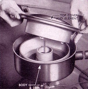
Oil Bath Type Air Cleaner
To clean, remove the air cleaner, unscrew the
wing nut on the top cover and lift off the cover
and the cleaner element. Empty the oil and
thoroughly clean the body. Wash the air cleaner
element in petrol to remove the dust and dirt,
and refill the air cleaner body with fresh engine
oil up to the level of the arrow stamped on the
side. Check that the cork gaskets are in good
condition, refit the element and the cover. Refit
the air cleaner to the carburettor. |
 |
Dry Gauze Type Air Cleaner
To clean, remove the air cleaner by slackening
the clamp securing it to the carburettor. Pour a
small amount of petrol into the cleaner via a
larger diameter aperture (where the carburettor
connection hose is fitted), swill round and pour
out of the “spout”. This procedure
should always be adopted, otherwise the tendency
will be to wash the dirt in the cleaner further
into the gauze. The element should be lightly
oiled, adopting the same procedure, any surplus
oil being allowed to drain off. Refit the air
cleaner to the carburettor. |
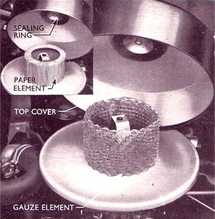 |
Paper
Element Type Air Cleaner
This is very similar to the wet type of air
cleaner, but instead of having a gauze element it
has a special paper one. This paper element must
not be washed or oiled. Stand the element
vertically and tap it on a firm flat surface
while slowly rotating it. Check the element for
tears in the paper or signs that it is so clogged
that the tapping treatment will not clear it.
Renew the element if it is defective. |
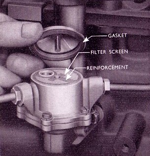 |
Clean the Fuel Pump
(Anglia)
This is mounted on the right hand side of the
cylinder block, is entirely automatic in action
and can be one of two types. One type had a domed
metal cover and the other an inverted glass
sediment bowl.Domed Cover Type
To service the domed cover type, remove the screw
from the top of the pump and detach the cover and
filter screen. Clean any sediment from the pump
body. Clean the screen in petrol and replace it
on the fuel pump body with the reinforcement
upwards. Check the gaskets to ensure that they
are in good condition and will make an airtight
joint. Renew the gaskets if necessary. Refit the
domed lid and tighten the screw.
|
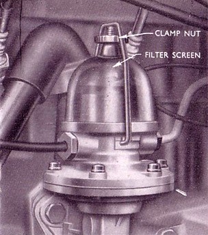 |
Glass Sediment Bowl Type
To service the glass sediment bowl type pump,
slacken the clamp nut at the top of the pump and
remove he bowl and filter screen. Clean any
sediment from the pump body. Clean the screen in
petrol and replace it on the fuel pump body with
the reinforcement upwards. Check the gasket to
ensure that it is in good condition and will make
an airtight joint. Renew the gasket if necessary.Replace the glass sediment
bowl and tighten the clamp nut
|
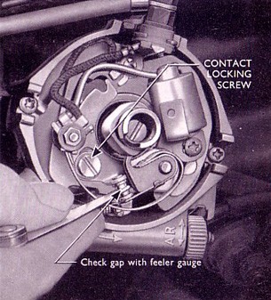
Clean and Adjust Contact
Breaker Points
Check the contact breaker points gap with a
feeler gauge, and adjust to compensate for wear
on the breaker arm, which is sometimes indicated
by misfiring at low speeds. The contact breaker
points should be set so that when the fibre arm
of the moving contact is on the highest point of
the cam, there is a gap of 0.014 in to 0.016 inThis
gap can be adjusted by slackening off the locking
screw on the fixed contact point and moving the
contact point until the gap is within the above
limits. The fixed contact point can be moved by
inserting a screwdriver in the recess provided
and twisting slightly.
Tighten the lock screw securely and recheck the
gap, as it may have altered slightly when
tightening up the screw.
If
the contact points are worn, pitted or badly
burned, they should be dressed flat with an
oilstone (or replaced).
Badly burned
points are often an indication of a faulty
condenser or oil on the points.
|
 |
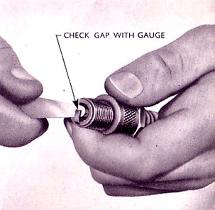
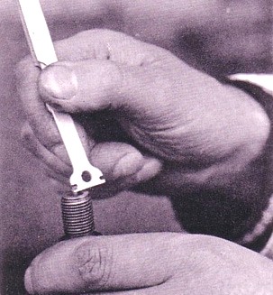
Clean and Adjust Sparking
Plugs
Remove a sparking plug. Clean the insulator body
of the plug with a clean dry cloth. Using an
appropriate tool, clean the end of the spark plug
to remove any deposits. Check the plug gap with a
feeler gauge. The plug gaps should be set at
0.023 in to 0.28 in (0.59 to 0.71 mm). If after
checking the gaps with a feeler gauge, it is
found that adjustment is necessary, the outer
point should be either bent forward or away from
the centre electrode, to increase or decrease the
sparking plug gap. Refit the sparking plug.NOTE
– Do not bend the centre electrode.
|
 |
Clean
the Distributor Cap
Use a soft clean cloth to wipe any dirt or oil
off the HT leads, the rotor arm and distributor
cap (both inside and out). Once the distributor
cap is clean, examine it for wear, cracks,
tracking or a worn our carbon bush. If any of
these faults are found fit a new cap.Check and Adjust
Ignition Timing (if necessary)
Ignition timing can be checked, and corrected if
necessary, by your Authorised Ford Dealer. The
modern equipment he carries for this purpose
enables him to do this work very quickly and
accurately. Remember that if the distributor has
been removed from the vehicle for any reason, it
is essential that it is refitted in its original
position.
However, if circumstances
prevent you having the ignition timing checked by
a Dealer, then proceed in the following manner:-
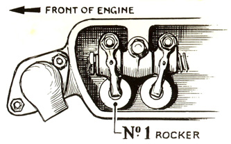
Remove No 1 cylinder spark
plug, partially cover the orifice with the thumb,
and rotate the engine until No 1 piston is on
compression stroke. You will feel the air
pressure on your thumb increase as the piston
rises on compression stroke, and stop rotating
the engine when the “notch” on the rim
of the crankshaft pulley and the pointer on the
timing chain cover are in line.
|
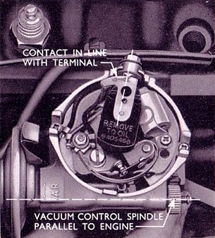
| Before refitting the distributor to
the engine, hold the body so that the vacuum
control spindle is parallel to the engine and set
the rotor metal contact in line with the low
tension terminal. Now refit the distributor, when it
will be observed that the rotor arm rotates
towards the condenser as the helical gears
engage.
Secure the body clamp to
the block, by means of the screw and lock washer.
Check that the advance adjustment nut is such
that the manual adjustment scale is at the zero
setting, i.e. set the knurled nut to the fourth
line on the graduated scale.
Rotate the
distributor in a clockwise direction to take up
any backlash in the drive, until the contact
breaker points are just about to open and lock
the distributor body clamp by tightening the nut
and bolts. To check that the distributor has been
correctly re-fitted, when replacing the cap,
ascertain that the rotor arm is facing No 1
cylinder contact in the cap.
|
 |
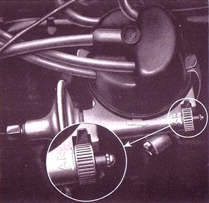
Varying Ignition Settings
for Different Fuels
By rotating the knurled distributor advance
adjustment nut it is possible to turn the contact
breaker base plate slightly, so either advancing
or retarding the ignition.It is often advantageous
however, to obtain the optimum ignition setting
taking into account the characteristics of a
particular engine and the brand of fuel in use by
means of the road test procedure.
An additional check and to
obtain the best results from any particular brand
of fuel, the car should be tested on the open
road (when fully “run in”).
Carefully note, by stop
watch, the time taken to accelerate from 30 mph
to 50 mph in top gear with the throttle fully
open. The optimum ignition setting is that which
gives the shortest possible time to accelerate.
It
must be remembered however, that only small
deviations from the normal setting outlined above
are necessary to effect this compensation. Do not
carry out indiscriminate adjustments.
A premium grade of
fuel muse be used in engines fitted with the
standard cylinder head. Normal grade fuel used
with the optional low compression head requires
no alteration to ignition timing.
|
 |
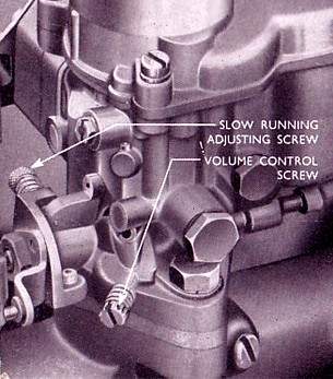
Carburettor Adjustment
The only adjustments required are to the volume
control screw and the slow running adjustment
screw.Idling adjustment must be
carried out when the engine is hot as follow:-
Screw in the slow running adjustment screw until
the idling speed is a little faster than normal.
Unscrew the volume control screw until the engine
begins to “hunt”
Screw the volume control screw in again until the
engine runs evenly. If the engine speed is then
too high, unscrew the slow running screw until a
reasonably slow idling speed is obtained. This
may cause a slight resumption of
“hunting”.
If so screw in the volume control screw until the
idling is perfect.
Note that the volume control screw
alters the volume of mixture passing into the
engine. Screwing it in reduces the volume of
mixture and screwing it out increases the volume.
It may also be necessary to make an
alteration to the distributor timing, in order to
obtain satisfactory idling.
Do not expect a
new engine to idle perfectly at low speeds until
various machined surfaces have had a chance to
“run themselves in”.
|
 |
Check
the Valve Clearances and Adjust (if
necessary)
Open the bonnet and listen to the engine
carefully. If there is a clattering sound from
the top of the engine, and the sound increases
both in loudness and noise as the engine speed is
increased, then it is best to check and adjust
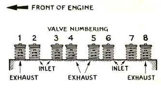
the valve clearances. Each cylinder has a pair of
valves; one inlet and one exhaust, and each valve
is operated by its rocker arm.
To check or adjust the valve clearances, remove
the valve rocker cover by undoing the four
retaining screws. Be careful not to damage the
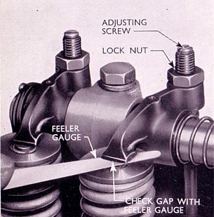
rocker cover gasket.The valve clearance
adjusting screws will then be exposed, and the
clearance should be adjusted to 0.010 in (0.254
mm) for the inlet valves and 0.017 in (0.432 mm)
for the exhaust valves, with the engine at normal
operating temperature.
In
order to ensure that each valve is fully closed,
check as follows:-
|
Valves Open
1 and 6 .. .. .. .. .. .. .. .. .. .. .. .. .. ..
.. .. .. .. .. .. .. .. ..
3 and 8 .. .. .. .. .. .. .. .. .. .. .. .. .. ..
.. .. .. .. .. .. .. .. ..
2 and 4 .. .. .. .. .. .. .. .. .. .. .. .. .. ..
.. .. .. .. .. .. .. .. ..
5 and 7 .. .. .. .. .. .. .. .. .. .. .. .. .. ..
.. .. .. .. .. .. .. .. ..
Exhaust Valves Nos 1, 4, 5 and 8 |
Valves to Adjust
3 and 8
1 and 6
5 and 7
2 and 4
Inlet Valves Nos 2, 3, 6 and 7 |
| To adjust a rocker, slacken off the
adjusting screw locknut and insert a feeler blade
between the toe of the rocker and the valve end.
Turn the adjusting screw until the correct
clearance has been obtained and tighten the
locknut. Recheck the gap after tightening the
locknut to make sure it hasn’t moved. When
replacing the rocker cover ensure that the gasket
is correctly positioned on the cylinder head to
avoid oil leaks.
|
 |
Clean Repack and Adjust
Front Wheel Bearings
Jack up the car and remove the hub cap (described
in the section General Maintenance - Wheels and
Tyres), Remove the dust cap by carefully levering
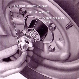
it from the end of the hub.Withdraw the spilt pin,
unscrew the bearing adjusting nut; remove the
thrust washer and the taper roller bearing. Lift
off the drum and wheel assembly.
Clean all the old
grease from these components and repack with good
quality wheel bearing grease. The grease should
be worked carefully into the rollers and cages of
the inner and outer bearings. The hub itself
should not be packed completely full but an
appreciable air space should be left.
Replace the hub
and bearing on the spindle followed by the flat
washer and castellated nut.
|
 |
| Tighten
the bearing adjusting nut to 30lb ft (4.1 kg m)
whilst rotating the wheel, and then slacken off
the nut back not less than two castellations and
not more than two and a half castellations. If
you do not own a torque wrench, rotate the wheel
whilst tightening up the bearing adjusting nut
until a heavy drag can be felt, then turn the nut
back one castellation at a time until the wheel
is perfectly free from just perceptible end
float. This is best tested at the periphery of
the wheel.
Fit
a new split pin; two holes are drilled in the
wheel spindle to allow adjustment to one-twelfth
of a turn. Carefully clean and replace the dust
hub cap, and then lower the vehicle to the
ground, check the wheel nuts and replace the hub
cap.
Never run the car
with the dust caps missing since this would allow
an easy entry for grit and other road dirt.
|
Reposition the Road Wheels
(if necessary)
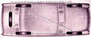
It is recommended that the wheels are changed
around from time to time to equalise tyre wear as
follows:Spare
to left front, left front to left rear, left rear
to right front, right front to right rear and
right rear to spare wheel compartment. If no
spare is available, the tyres should be
repositioned by moving the rear wheels to the
front and putting the right front wheel on the
left rear hub and the left front wheel on the
right rear hub.
|
|
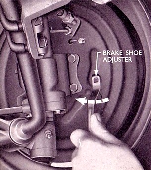
Adjusting the Front Brakes
Before making a brake adjustment, ensure that all
four tyres are inflated to the correct pressure.In order to test the
brakes, select a good stretch of road surface,
preferably dry and uncambered. If the braking
action is unequal, or the pedal movement is
excessive, the brakes should be adjusted. Your
Authorised Ford Dealer can make this adjustment
quickly, correctly and economically. If such
service is not readily available, the brakes may
be adjusted for lining wear as follows (it is
advisable to test the front wheel bearings and adjust if necessary)
Check that the
hand brake is in the fully released position and
that the brake drums are cold. There are two
square headed adjusters on each front brake plate
to enable each shoe to be adjusted individually.
Jack
up the
front wheels, turn the adjuster of one shoe
clockwise (using hand pressure) until the drum is
locked, then slacken back to obtain minimum
running clearance.
Repeat this
procedure on the second adjuster, also on the
other front brake.
|
 |
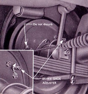
Adjusting the Rear Brakes
On each rear brake, a threaded square headed
adjuster is fitted diametrically opposite the
expander unit.Do
not disturb the plain square headed adjuster
positioned on the backplate, your Authorised Ford
Dealer should make this adjustment when it
becomes necessary.
Jack
up the
rear wheels, turn the threaded adjuster clockwise
until the drum is locked, then slacken back to
obtain minimum running clearance. Similarly
adjust the other rear brake.
Do
not jeopardise your safety by makeshift
replacements or adjustments.
It is also of
extreme importance that the linings are kept free
from grease and oil. The use of correct front
wheel bearing lubricant and care not to overfill
the rear axle, as well as replacing grease
retainers when leakage is indicated, will prove
particularly valuable in maintaining braking
efficiency.
|
 |
Check the
Brake Lines
Check the brake flexible hoses for signs of
perishing or chafing. Check the metal brake lines
for corrosion, dents or leaks. If any defect is
found, take your vehicle to your Authorised Ford
Dealer for repair as soon as possible. |
Information taken from Various Ford
Anglia Instruction Books and Handbooks.
Warning -
The Health and Safety bit.
Please note your health may be at
risk if you do not take sensible safety
precautions. Never work under an unsupported
vehicle, do not take shortcuts. If you feel that
the task is beyond your capabilities, then employ
the services of a trained professional. The Owner
of this Website nor the author cannot be held
responsible for any accidents or injury arising
from advice given on this webpage. Safety advice
can be obtained from the RoSPA.
|

|
|