You are in:


GPO
Vans |

Ford
Anglia 307E Van Photo's - GPO - Album No 2
Shown below
is a copy of a GPO Instruction detailing the Ford Anglia
Van.
| TELECOMMUNICATIONS
INSTRUCTION |
J TRANSPORT AND
MECHANICAL AIDS
2 Vehicle Data |
MOTOR TRANSPORT
Minor
Van, Type 4 (Ford)
| 1. General -
This Instruction describes the Minor Van,
Type 4 (Ford). It is fully
interchangeable with other types of Minor
Van, the types of duties for which these
are intended being given in B 3550. 2. Description
- The vehicle is a modified Ford light
van of welded pressed-sheet-metal
construction. The overall dimensions are:
length 12 ft. 6 in., width 4 ft. 11 ¼
in. and height 5 ft. 4 ½ in.
A general
view of the vehicle is shown in Fig 1.
Cab and body sections are separated by a
wire-mesh partition as shown in Figs. 2
and 3, to enable the body to be locked
without restricting access to the cab
(see par. 14). Accommodation is provided
externally for an extension ladder and
internally for a step ladder, pruning
rods, tools, stores, E.I.s etc. The rear
doors are fitted with hook and eye door
stays which should always be used when a
door is open to avoid minor accidents due
to doors swinging in the wind.
3.
Ladder carrier - A horizontal type of
ladder Carrier is provided on the roof
for a Ladder, Extension, No. 4, 4A or 5.
At the rear end of the carrier a roller
is fitted to facilitate the placing and
removal of the ladder.
|
The roller should
be oiled periodically to ensure smooth
and easy rotation. The ladder should be
secured at the front and the rear by the
straps provided for this purpose, and
should be so positioned that the ladder
does not overhang the rear of the
vehicle. To allow for the difference in
the bottom rung position on the various
types of extension ladders Nos. 4, 4A and
5, two sets of staples for anchoring the
ladder securing straps are fitted on the
ladder carrier. Only one extension ladder
of the specified type may be carried on
the ladder carrier and, except for the
special provision mentioned in pars. 11
and 12, nothing else may be carried on
the roof or on the ladder carrier. 4. Cab -
Seats in the cab provide for one
passenger in addition to the driver, the
driver’s seat being adjustable. Two
wire-mesh containers for E.I.s, log
sheets, diagram folders, works and other
papers are mounted on the wire-mesh
partition, one container being positioned
behind each seat. The vehicle tool box is
located immediately behind the
passenger’s seat.
A hat and
coat hook is provided in a central
position on the partition behind the
seats. The fire extinguisher is
accommodated in the cab.
|
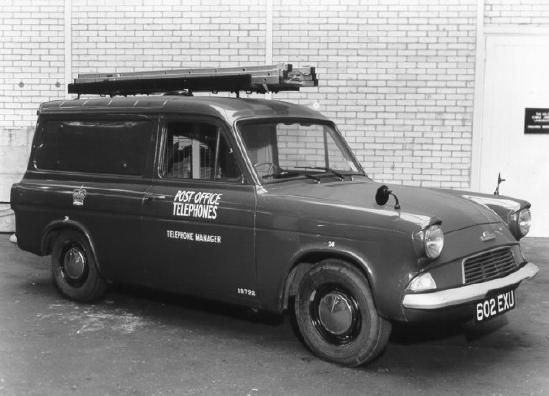
Fig.
1
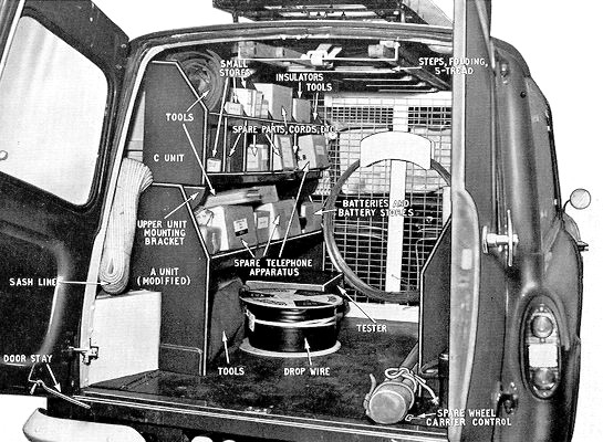
Fig.
2
| 5. Step ladder
accommodation - Steps, Folding,
5-tread (see par. 6) may be carried
within the body where they are secured by
a strap, in a central position
immediately under the roof (Fig. 2). The
aperture at the top of the partition,
through which the steps must pass, is
provided with a separate hinged wire mesh
panel as a security measure when steps
are not carried. To clear the aperture
for the accommodation of steps, only the
top fastening of the wire-mesh panel
should be undone; the panel will then
hinge downwards. When the folding steps
are being inserted, place the top of the
steps on the lower edge of the aperture
in the dividing partition; raise the
bottom of the steps as near to the
horizontal as possible and push them
forward until the top of the door framing
and the rear support for the steps can be
cleared; lift the bottom of the steps
fully up under the roof and pull the
bottom of the steps back into the rear
support; then fasten the steps securely
to the rear support with the strap
provided. The foregoing procedure should
be reversed to remove the steps. 6. Requisitions
for Steps, Folding, 5-tread for use on
these vans should be endorsed
‘Folding tread type required’.
|
7. Rack units
- Accommodation for stores and tools is
provided by rack units which can be
fitted on either side of the interior of
the body and which are illustrated in
Fig. 5. When the van is supplied A units
only are fitted, the near-side unit being
modified to fit over the petrol tank
housing. B and C units are available as
optional fitments, being mounted on top
of the A units as shown in Fig. 2, using
the right-angle brackets which are
supplied with the vehicle. The brackets
supplied with the upper units should be
retained.
If, on certain duties, less rack
accommodation than the initial two A
units is required and extra clear floor
space is necessary, one or both A units
may be removed (see also par. 9).
Figs. 2 and 3 show a typical layout for
the load carried by a rural territorial
maintenance officer. Owing to the many
variations in the circumstances under
which minor-type vans may be employed it
is not practicable to lay down any
specific layouts. Much must be left to
the good sense of each officer concerned
in making the best use of the facilities
available. The principle of keeping heavy
items on the lowest level possible should
always be observed. Telephone
instruments, spare parts, cords, small
stores etc. |
| should be carried
in suitable cartons to prevent chafing
and rattling, and every effort should be
made to utilize the special containers
available for certain items, e.g. Gloves,
IR. and Dials, Automatic. 8. Supply of
additional rack units - When
additional units are required,
requisitions for Minor Van Fitting, Unit
A, B or C should be forwarded to the
Supplies Dept. On receipt of the
additional items an appropriate entry
should be made on the vehicle tool list
(A 1112).
9.
Recovery of rack units - Standard
units surplus to requirements should be
returned to the Supplies Dept. direct and
surplus modified A units scrapped
locally, the vehicle tool list being
amended accordingly. The special nuts
(Simmonds elastic stop nuts) provided for
the set screws securing the component
units together should not be used for
other purposes but should be secured to
their relevant units and returned,
together with the brackets originally
supplied with the B and C units, to the
Supplies Dept.
The top unit mounting brackets originally
supplied with the vehicle must be
retained on the vehicle to allow for
future changes in rack units requiring
their use.
|
10. Large
diameter coils of wire - A simple
saddle type of fitment mounted on the
rear of the vehicle cab/body partition is
provided as an aid to the tidy stowage of
large diameter coils of wire (Fig. 2). A
piece of twine or soft copper wire should
be used to secure the coil of wire to the
wire mesh of the partition and so prevent
chafing of the coil. 11. Pruning rods
- When pruning rods are carried they may
be placed on the floor of the vehicle,
their front ends being passed through the
aperture provided for this purpose in the
dividing partition (Fig. 3). The rear end
of the rods can then be secured to an
anchorage set in the vehicle floor beside
the rear support of the off-side A unit.
Alternatively, they may be carried on the
ladder carrier by means of brackets
bolted to the near-side of the ladder
carrier (see M 0048).
12.
Survey rods - Survey rods may be
carried on the ladder carrier in the same
manner as pruning rods (Fig. 4) but it is
essential that the set of survey rods be
equipped with the modified pruning rod
holster specified in M 0048, to ensure
that a rod cannot be dislodged in
transit.
|
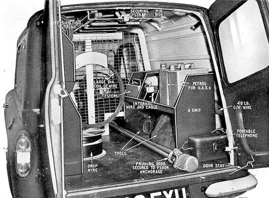
Fig.
3
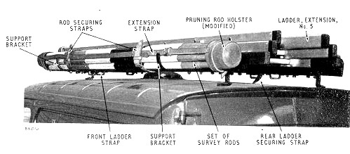
Fig.
4
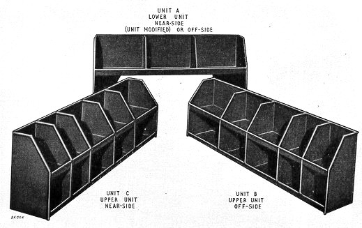
Fig.
5
| 13. Maximum
permissible load - The maximum load
that a Minor Van, Type 4 (Ford) may carry
without any fittings is 5 cwt. 2 qrs. 17
lb. (this excludes the weight of the
driver, which has been taken as 168 lb.).
Hence, if a passenger (average weight 168
lb.) is carried when two A units (each
weighing approx. 34 lb.) are fitted, then
the total weight of tools, stores etc.
must not exceed 397 lb. The B and C units
each weigh 26 lb. and the load carried
must be reduced accordingly when these
units are fitted. A periodical
examination should be made by the driver
to ensure that surplus items are not
carried and that the maximum permissible
load is not exceeded. A simple check can
be made by weighing the van in its moving
condition, i.e. with driver, passenger,
stores, tools, racks, petrol, oil etc.
The gross moving weight must not exceed
22 cwt. 3 qrs. 9 lb. Any weighbridge
charges involved should be passed to
Freight and Cartage. 14. Locking
arrangements - Cab and rear doors are
equipped with FP 750 series locks to
enable the contents to be safeguarded
when the vehicle is left unattended for
short periods. For extended absences
additional security can be obtained by
padlocking the rear doors. A hasp and
staple are fitted to the rear doors for
this purpose. The vehicle tool box is
also equipped with a hasp and staple.
Padlocks, 1¼ in. are the correct
padlocks for use on this class of
vehicle.
|
[NOTE:-
Padlocks, 1¼ in. are sometimes of the
spring self-locking type. To prevent the
accidental locking of keys inside the van
body, it is recommended that the padlock
keys should not all be carried together.]
A spring clip is fitted on the rear door
to prevent chafing by the padlock.15. The spare
wheel - The spare wheel is housed
beneath the rear of the body floor in a
drop-front type of carrier which is
raised or lowered by rotating the
hexagonal head set in the rear off-side
of the floor (Fig. 2), using the wheel
brace.
16.
Towing - Minor Vans, Type 4 (Ford)
are not suitable for towing any type of
trailer or for use as a power unit to
assist working operations, and officers
are forbidden to use or attempt to use
the vehicle for these purposes.
17.
Re-enamelling or retouching - The
outside of the van has a synthetic enamel
finish. Attempts to retouch any scratched
or damaged parts should not be made by
the staff using the vehicle. Work of this
nature will be undertaken by the Workshop
Supervisor / Mechanic-in-Charge when
necessary and during periodic overhauls.
18.
Signwriting - Standard inscriptions
for signwriting are given in C 0015.
19.
Speed limit - See D 0022.
|
END
|
  
|
|